Kite Buggy Plans
YES, here they are, your search is over, people are always asking for buggy plans on the forums.
PTW Cougar 2 The first set of plans for the PTW Cougar 2 contain everything you need, the plans have been CAD up and also come with the DFX files for having the plate work laser/water jet cut, these plans come as a package.
PTW Dominator 1 Plans of the Dominator 1 buggy, were made by a buggy enthusiast who wanted to make a Dominator buggy, he travelled to my Gaff to see the Dominator first hand and take some measurements so he could make his own, in return for this he would give us a set of his drawings, and by clicking the link you will find them.
Other Plans These are plans I have come across on the internet over the years, they are not mine and if the owners should wish them to be removed, they will be at once.
In the mean time, here you go buggy builders….get building
——————————————————————-
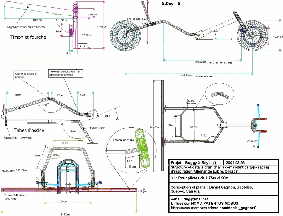
Advanced cadded plans of a race type buggy
PTW Cougar 2 Plans
————————————————————————————–
PTW Dominator 1 Plans
——————————————————————-
Other Plans
-
- PL Classic Buggy 5
-
- PL Classic Buggy 4
-
- PL Classic Buggy 3
-
- PL Classic Buggy 2
-
- PL Classic Buggy 1
-
- Plans 5

-
- Plans 3
-
- Plans 2
-
- Plans 4
-
- Plans 1
-
- Buggy Plans 8
-
- Buggy Plans 7
-
- Buggy Plans 6
-
- Buggy Plans 5
-
- Buggy Plans 4

-
- Buggy Plans 3
-
- Buggy Plans 2
-
- Buggy Plans 1
-
- Kite Buggy Plans 2
-
- Kite Buggy Plans 1

The buggy.
The buggy looks a lot like the peter Lynn Classic
Materials & Tools:
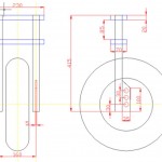
1. 3x Wide buggy wheel from the kite shop (ready) or the pvc wheel of a barrow (needs some work to fit bearings) from the hardware store.
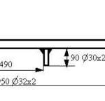
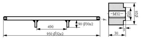
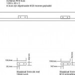
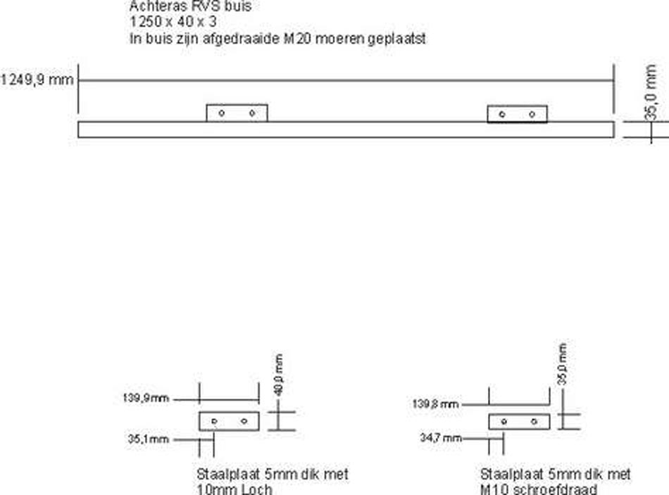
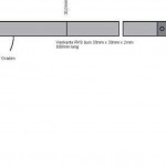
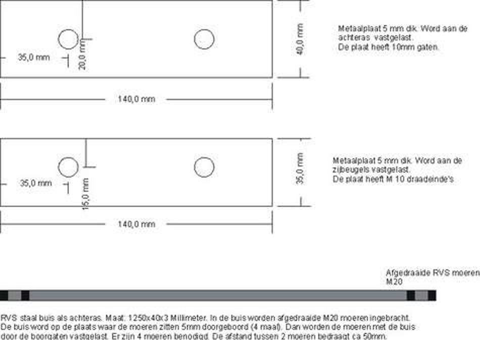
2. Rear-axle:1x 950 mm tube dia. 32×2 mm,2x 30 mm rod dia. 28 mm, full,2x Bolt M12 – 100 mm with spring-ring,2x 90 mm tube dia. 30×2 mm.
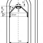
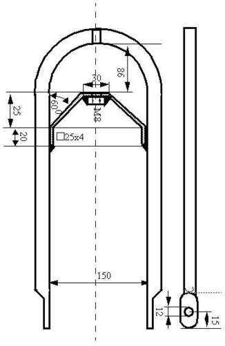
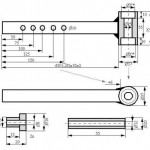
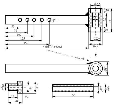
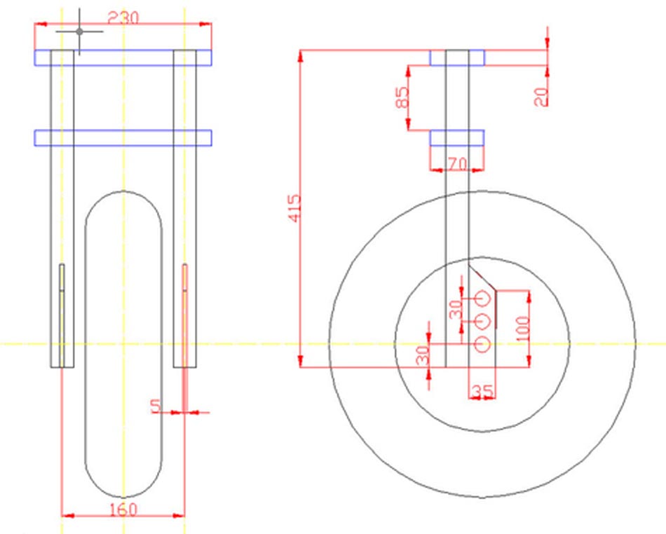
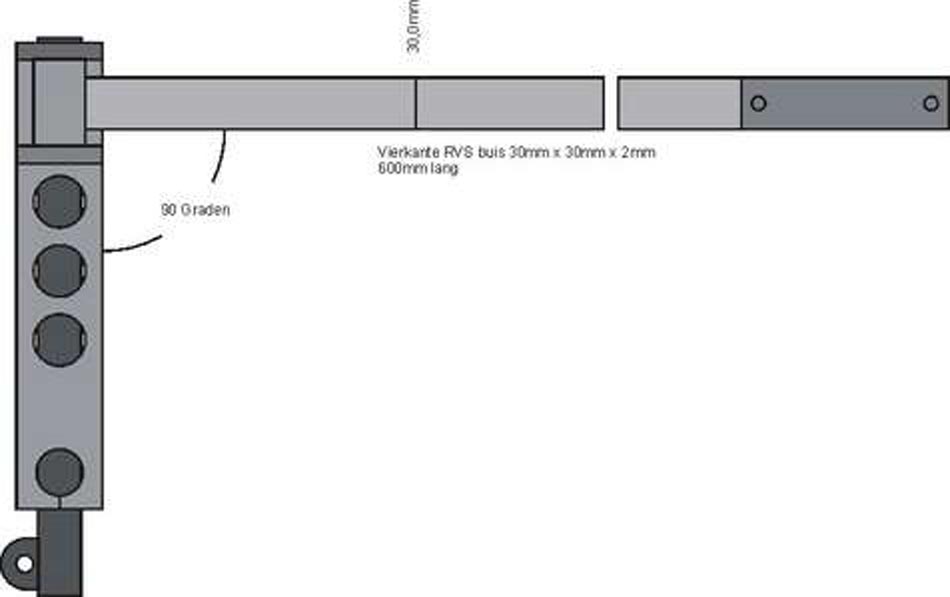
3. Balhead:1x 456 mm square-tube 32x32x2 mm,1x 75 mm rod dia. 37 mm, full,2x 20 mm rod dia. 16 mm, full,1x 55 mm tube dia. 20×4 mm.
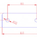
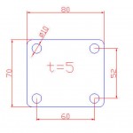
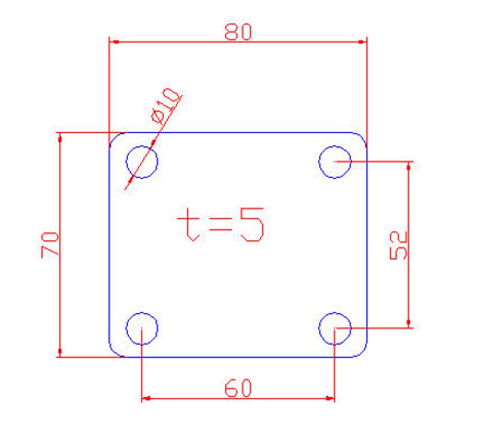
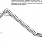
4. Frame Tube’s: 2x 780 mm tube dia. 25×1.5 mm,2x sheet 100x70x4 1x Bolt M8 – 55 mm with 1x M8 nut and spring-ring.
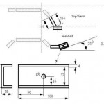
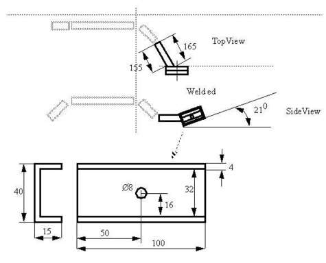
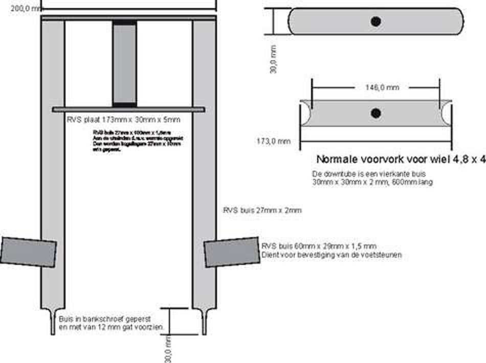
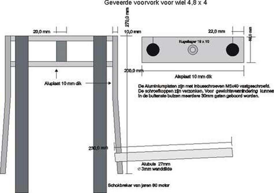
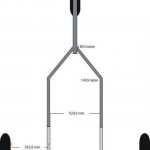
5. Front Fork: 1x 850 mm tube dia. 25×3 mm,1x sheet 220x25x4 mm,2x 37 mm tube 16×2 mm,2x 260 mm tube dia. 16×1.5 mm,1x Bolt M8 – 125 mm with 1x M8 nut,1x Bolt M12 – 180 mm with 2x spring-rings and 1x M12 nut.2x ballbearings 8x32x12. Stainless and seawater-resistent and sand-resistent !!!
6. Bending tool, Welding tool for stainless steel, powered polish tools.
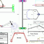
Building
1. Rear-axle:I don’t know if the tube-in-tube connector on the rear-axle is strong enough. Maybe it needs side-support on each side of the connectors. The tube-in-tube connection (foto) with the frame-tube has a 1 mm tolerance between the tubes.
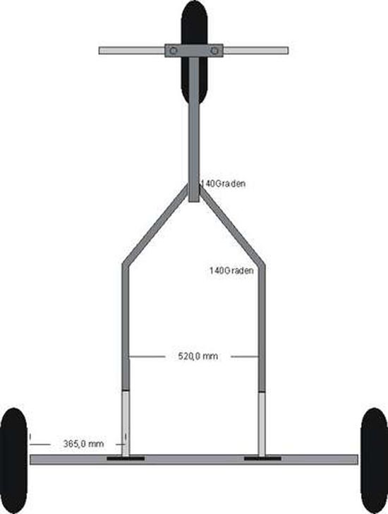
2. Balhead (downtube):The square tube must be at least 2 mm thick. For many wheelies and Big Foot TIRES, 1.5 mm is to WEAK !!. The big X diameter, in the drawing, is the outside diameter of the ballbearing. Head and bearing MUST form a light press fitting.
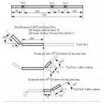
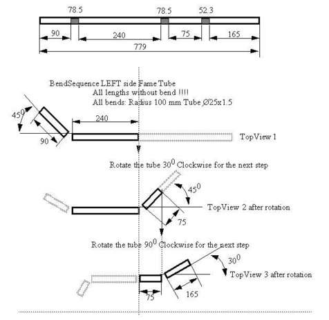
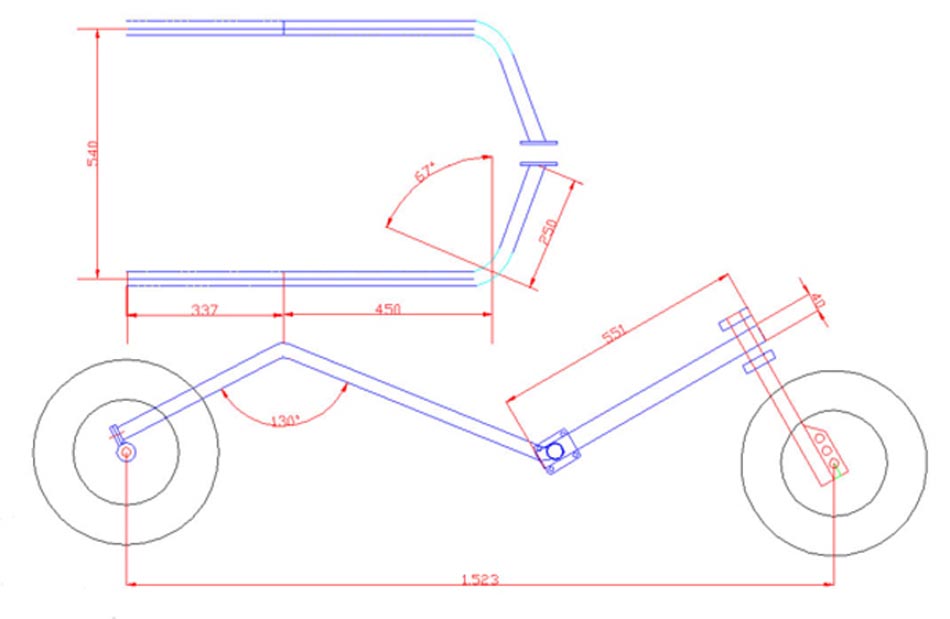
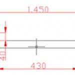
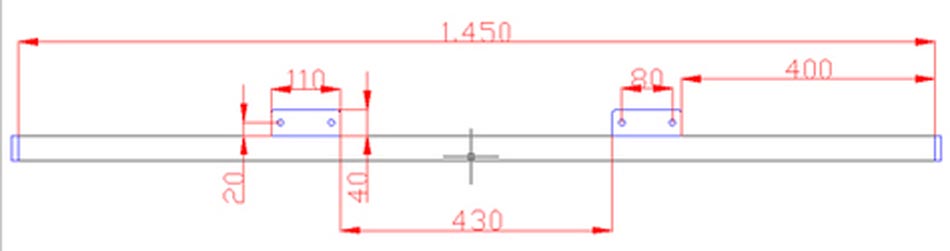
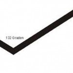
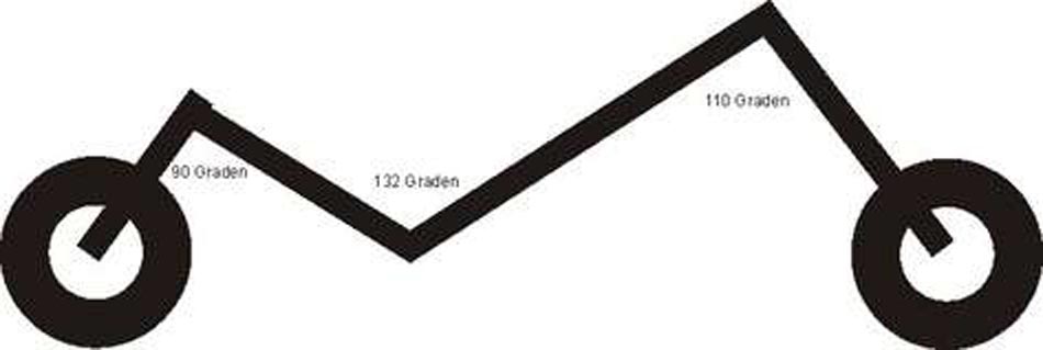
3. Frame Tube (side frame) :The frame tube must slide easy into the connector of the rear-axle. Therefor the tube-in-tube connection with the rear-axle has a 1 mm tolerance between the tubes.The curve’s in the bend-sequence-drawing are omitted. Only the staight tube sections are drawn.
So, remember first go straight .. mm then bend .. degrees. Then rotate .. degrees. See the drawing. The right-frametube is a mirror of the left-frametube. You can make it easy by reversing the bend sequence. Start at the end (3) of the bend sequence and work to the start (1). That is all. Rotations of the tube are OK. Test this with a thin pvc tube (electical) or some steel wire. Form the 4mm thick sheet into a U-shape. Weld the fitted 8M bold to one of the U-shape’s (foto).
4. Front Fork: Weld the V-shaped centre part to the fork over the full 20 mm (4 times). Weld also the 8M nut to the V-shaped centre part. The 30 mm fork end’s are flattened (squeezed together) tube end’s (foto). The 2 pieces of tube (37x 16x2mm) are needed to keep the front wheel in the middle of the front fork.
5. The seat to fit the buggy.